
1 Prepare before assembly
1.1 Ensure that the flange connection selected as ISO 6162-2 meets the requirements of the application (e.g. rated pressure, temperature etc.).
1.2 Ensure that the flange components (flange connector, clamp, screw, O-ring) and ports conform to ISO 6162-2
1.3 Ensure the correct screws, metric for type 1 and inch for type 2.
1.4 Ensure do not mix the components with ISO 6162-1 parts. How to identify the different see “How to identify ISO 6162-1 and ISO 6162-2 flange connection and components” link.
1.5 Ensure that all sealing and surface interfaces (include port and flange components) are free of burrs, nicks, scratches and any foreign material.
2 How to assemble correctly
2.1 To help minimize O-ring scrub-out, lubricate the O-ring with a light coat of the hydraulic fluid used in the system or a compatible oil, when necessary. Take special care, as excess lubricant can seep out of the joint and lead to a false indication of leakage.
Note: O-ring sizes see table 1 or table 2, and it is same size for metric or inch screw, it is same size for ISO 6162-1 and ISO 6162-2 flange connections, no mixed issue.
2.2 Position the flanged head and the flange clamps.
2.3 Place the hardened washers on the screws, and place the screws through the holes in the clamps.
2.4 Hand tighten the screws in the sequence shown in Figure 1 to ensure uniform contact at all four screw locations to prevent the flange tipping, which can lead to the flange breaking during application of final torque.
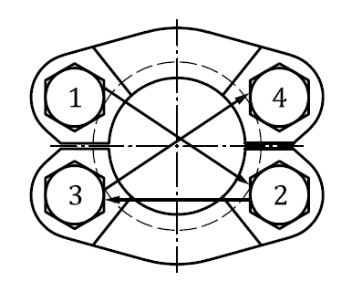
Figure 1 — Screw tightening sequence
2.5 Torque the screws in the sequence shown in Figure 1 in two or more increments to the recommended screw torque level and using the relevant wrench sizes in table 1 for metric screw and table 2 for inch screw.
Table 1 — Torque and wrench sizes with metric screw for assembling flange connections that conform to ISO 6162-2
|
Nominal size |
Maximum working pressure |
Type 1 (metric) |
||||||||
|
Screw Thread |
Screw length mm |
Screw torque N.m |
Wrench |
O-ring |
||||||
|
MPa |
bar |
for hexagon head screw mm |
for socket head screw mm |
Code |
Inside diameter mm |
Cross -section mm |
||||
|
13 |
42 |
420 |
M8 |
30 |
32 |
13 |
6 |
210 |
18.64 |
3.53 |
|
19 |
42 |
420 |
M10 |
35 |
70 |
16 |
8 |
214 |
24.99 |
3.53 |
|
25 |
42 |
420 |
M12 |
45 |
130 |
18 |
10 |
219 |
32.92 |
3.53 |
|
32 |
42 |
420 |
M12 |
45 |
130 |
18 |
10 |
222 |
37.69 |
3.53 |
|
38 |
42 |
420 |
M16 |
55 |
295 |
24 |
14 |
225 |
47.22 |
3.53 |
|
51 |
42 |
420 |
M20 |
70 |
550 |
30 |
17 |
228 |
56.74 |
3.53 |
|
64 |
42 |
420 |
M24 |
80 |
550 |
36 |
19 |
232 |
69.44 |
3.53 |
|
76 |
42 |
420 |
M30 |
90 |
650 |
46 |
22 |
237 |
85.32 |
3.53 |
Table 2 — Torque and wrench sizes with inch screw for assembling flange connections that conform to ISO 6162-2
|
Nominal size |
Maximum working pressure |
Type 2 (inch) |
||||||||
|
Screw Thread |
Screw length mm |
Screw torque N.m |
Wrench |
O-ring |
||||||
|
MPa |
bar |
for hexagon head screw in |
for socket head screw in |
Code |
Inside diameter mm |
Cross -section mm |
||||
|
13 |
42 |
420 |
5/16-18 |
32 |
32 |
1/2 |
1/4 |
210 |
18.64 |
3.53 |
|
19 |
42 |
420 |
3/8-16 |
38 |
60 |
9/16 |
5/16 |
214 |
24.99 |
3.53 |
|
25 |
42 |
420 |
7/16-14 |
44 |
92 |
5/8 |
3/8 |
219 |
32.92 |
3.53 |
|
32 |
42 |
420 |
1/2-13 |
44 |
150 |
3/4 |
3/8 |
222 |
37.69 |
3.53 |
|
38 |
42 |
420 |
5/8-11 |
57 |
295 |
15/16 |
1/2 |
225 |
47.22 |
3.53 |
|
51 |
42 |
420 |
3/4-10 |
70 |
450 |
1 1/8 |
5/8 |
228 |
56.74 |
3.53 |
|
64 |
42 |
420 |
- |
- |
- |
- |
- |
232 |
69.44 |
3.53 |
|
76 |
42 |
420 |
- |
- |
- |
- |
- |
237 |
85.32 |
3.53 |
Post time: Jan-20-2022