
1 How to identify ISO 6162-1 and ISO 6162-2 flange port
See table 1 and figure 1, compare the key dimensions for identify ISO 6162-1 (SAE J518-1 CODE 61) port or ISO 6162-2 (SAE J518-2 CODE 62) port.
Table 1 Flange port dimensions
|
Flange size |
Flange port dimensions |
||||||||
|
ISO 6162-1 (SAE J518-1 CODE 61) |
ISO 6162-2 (SAE J518-2 CODE 62) |
||||||||
|
Metric |
Dash |
l7 |
l10 |
d3 |
l7 |
l10 |
d3 |
||
|
Metric screw |
Inch screw |
Metric screw |
Inch screw |
||||||
|
13 |
-8 |
38.1 |
17.5 |
M8 |
5/16-18 |
40.5 |
18.2 |
M8 |
5/16-18 |
|
19 |
-12 |
47.6 |
22.2 |
M10 |
3/8-16 |
50.8 |
23.8 |
M10 |
3/8-16 |
|
25 |
-16 |
52.4 |
26.2 |
M10 |
3/8-16 |
57.2 |
27.8 |
M12 |
7/16-14 |
|
32 |
-20 |
58.7 |
30.2 |
M10 |
7/16-14 |
66.7 |
31.8 |
M12 |
1/2-13 |
|
38 |
-24 |
69.9 |
35.7 |
M12 |
1/2-13 |
79.4 |
36.5 |
M16 |
5/8-11 |
|
51 |
-32 |
77.8 |
42.9 |
M12 |
1/2-13 |
96.8 |
44.5 |
M20 |
3/4-10 |
|
64 |
-40 |
88.9 |
50.8 |
M12 |
1/2-13 |
123.8 |
58.7 |
M24 |
- |
|
76 |
-48 |
106 |
61.9 |
M16 |
5/8-11 |
152.4 |
71.4 |
M30 |
- |
|
89 |
-56 |
121 |
69.9 |
M16 |
5/8-11 |
- |
- |
- |
- |
|
102 |
-64 |
130 |
77.8 |
M16 |
5/8-11 |
- |
- |
- |
- |
|
127 |
-80 |
152 |
92.1 |
M16 |
5/8-11 |
- |
- |
- |
- |
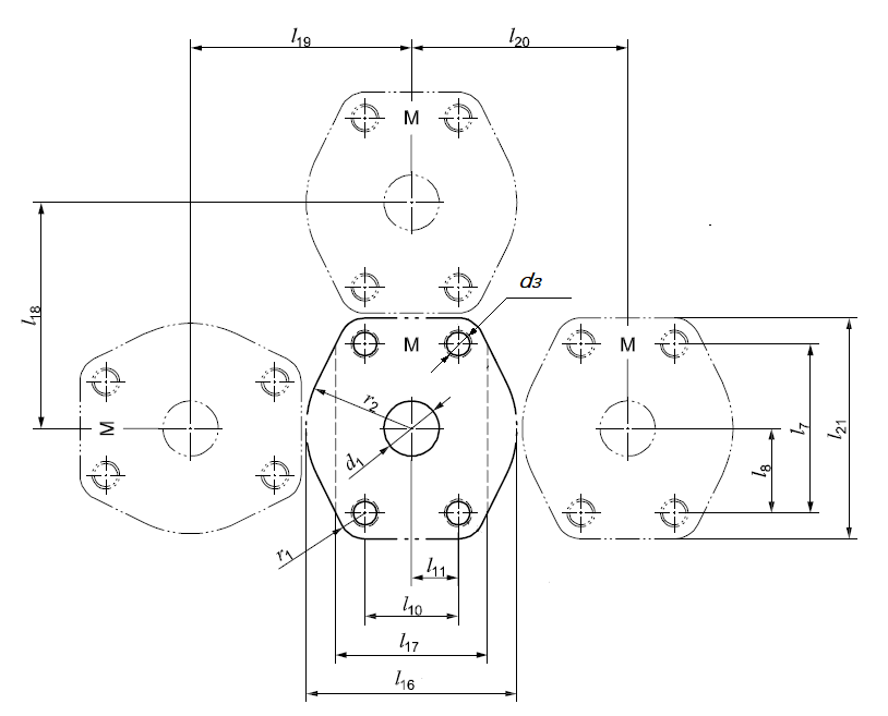
Figure 1 Port dimension for flange connections
From table 1, Dash-8 and -12 sizes, it is same screw dimensions and closely l7 and l10 for ISO 6162-1 and ISO 6162-2, so need inspect the l7 and l10 dimensions carefully, and measured with an accuracy of 1 mm or less.
2 How to identify ISO 6162-1 and ISO 6162-2 flange clamp
See table 2 and figure 2, figure 3, compare the key dimensions for identify ISO 6162-1 (SAE J518-1 CODE 61) flange clamp or ISO 6162-2 (SAE J518-2 CODE 62) flange clamp.
If it is split flange clamp, inspect and compare l7, l12 and d6 dimensions.
If it is one-piece flange clamp, inspect and compare l7, l10 and d6 dimensions.
Table 2 Flange clamp dimensions
|
Flange size |
Flange clamp dimensions (mm) |
||||||||
|
ISO 6162-1 (SAE J518-1 CODE 61) |
ISO 6162-2 (SAE J518-2 CODE 62) |
||||||||
|
Metric |
Dash |
l7 |
l10 |
l12 |
d6 |
l7 |
l10 |
l12 |
d6 |
|
13 |
-8 |
38.1 |
17.5 |
7.9 |
8.9 |
40.5 |
18.2 |
8.1 |
8.9 |
|
19 |
-12 |
47.6 |
22.2 |
10.2 |
10.6 |
50.8 |
23.8 |
10.9 |
10.6 |
|
25 |
-16 |
52.4 |
26.2 |
12.2 |
10.6 |
57.2 |
27.8 |
13.0 |
13.3 b |
|
32 |
-20 |
58.7 |
30.2 |
14.2 |
10.6 a |
66.7 |
31.8 |
15.0 |
13.3 |
|
38 |
-24 |
69.9 |
35.7 |
17.0 |
13.3 |
79.4 |
36.5 |
17.3 |
16.7 |
|
51 |
-32 |
77.8 |
42.9 |
20.6 |
13.5 |
96.8 |
44.5 |
21.3 |
20.6 |
|
64 |
-40 |
88.9 |
50.8 |
24.4 |
13.5 |
123.8 |
58.7 |
28.4 |
25 |
|
76 |
-48 |
106.4 |
61.9 |
30.0 |
16.7 |
152.4 |
71.4 |
34.7 |
31 |
|
89 |
-56 |
120.7 |
69.9 |
34.0 |
16.7 |
- |
- |
- |
- |
|
102 |
-64 |
130.2 |
77.8 |
37.8 |
16.7 |
- |
- |
- |
- |
|
127 |
-80 |
152.4 |
92.1 |
45.2 |
16.7 |
- |
- |
- |
- |
|
a, 10.6 for metric screw, and 12.0 for inch screw |
|||||||||
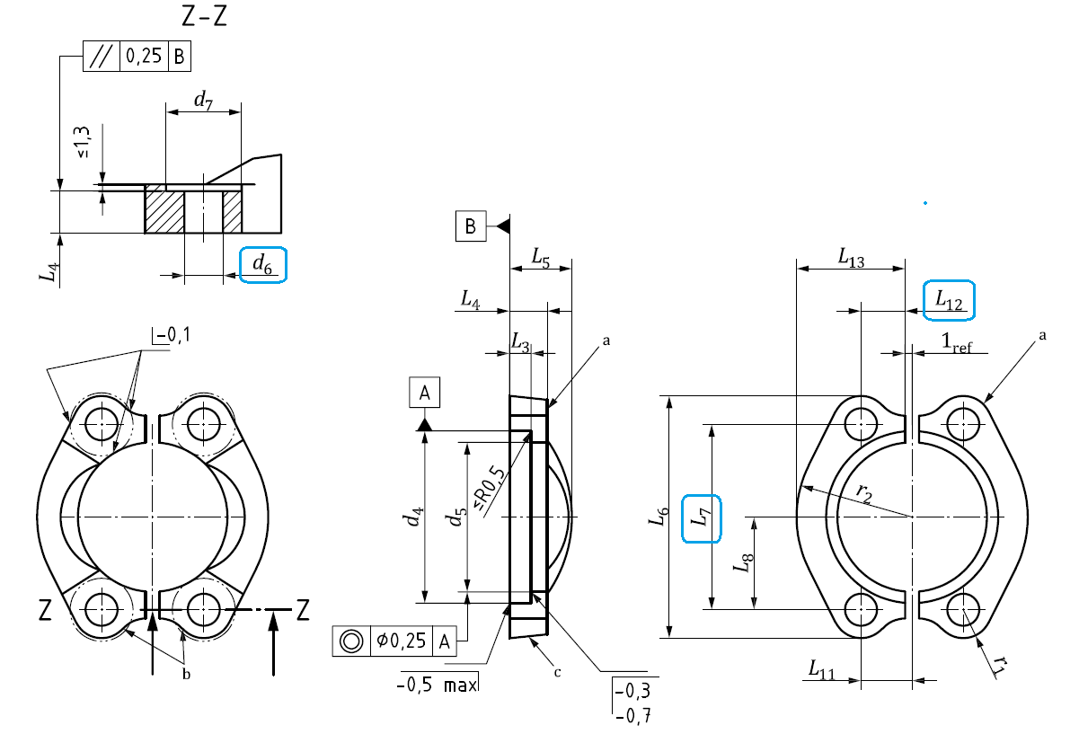
Figure 2 Split flange clamp
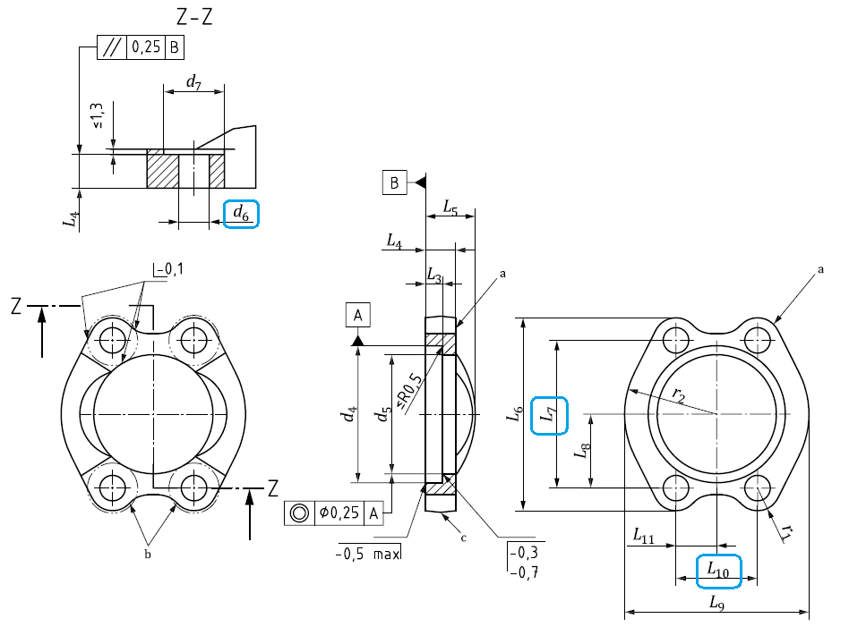
Figure 3 One-piece flange clamp
3 How to identify flange head
From table 3 and figure 4, compare the key dimensions for identify ISO 6162-1 (SAE J518-1 CODE 61) flange head or ISO 6162-2 (SAE J518-2 CODE 62) flange head.
And if there is an identification groove located on the circumference of the flange disk, see figure 4 blue marked, it is ISO 6162-2 flange head. (this mark is optional before, so not all of ISO 6162-2 flange heads have this mark)
Table 3 Flange head dimensions
|
Flange size |
Flange head dimensions (mm) |
||||
|
ISO 6162-1 (SAE J518-1 CODE 61) |
ISO 6162-2 (SAE J518-2 CODE 62) |
||||
|
Metric |
Dash |
d10 |
L14 |
d10 |
L14 |
|
13 |
-8 |
30.2 |
6.8 |
31.75 |
7.8 |
|
19 |
-12 |
38.1 |
6.8 |
41.3 |
8.8 |
|
25 |
-16 |
44.45 |
8 |
47.65 |
9.5 |
|
32 |
-20 |
50.8 |
8 |
54 |
10.3 |
|
38 |
-24 |
60.35 |
8 |
63.5 |
12.6 |
|
51 |
-32 |
71.4 |
9.6 |
79.4 |
12.6 |
|
64 |
-40 |
84.1 |
9.6 |
107.7 |
20.5 |
|
76 |
-48 |
101.6 |
9.6 |
131.7 |
26 |
|
89 |
-56 |
114.3 |
11.3 |
- |
- |
|
102 |
-64 |
127 |
11.3 |
- |
- |
|
127 |
-80 |
152.4 |
11.3 |
- |
- |
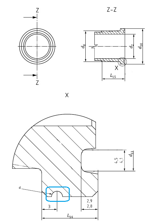
Figure 4 Flange head
Post time: Jan-20-2022