
There are 3 methods to assemble 24°cone connectors using cutting rings conforming to ISO 8434-1, detail see below.
The best practice regarding reliability and safety is achieved by pre-assembling the cutting rings using machines.
1How to assemble Cutting rings direct into 24° cone connectors body
|
Step |
Instruction |
Illustration |
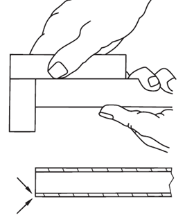
| Step 1:Preparation of tube | Cut tube off at a right angle. A maximum angular deviation of 0,5° relative to the tube axis is permissible. Do not use pipe cutters or cutting-off wheels as they cause severe burring and angular cuts. Use of a precision cut-off machine or device is recommended.Lightly deburr tube ends inside and out (maximum 0,2 × 45°), and clean them. ATTENTION — Thin-walled tubes may require supportive tube inserts. see manufacturer’s assembly instructions Deformation or irregularities such as inclined sawed-off tubes or excessively deburred tubes reduce the integrity, life expectancy and the sealing of the tube connection. |
 |
| Step 2:Lubrication and orientation | Lubricate thread and 24° cone of the body and the thread of the nut.Place nut and cutting ring on the tube with the cutting edge towards the tube end, as shown. Ensure that the cutting ring is facing the correct direction to prevent assembly error. | 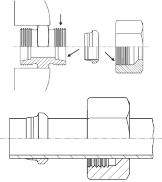 |
| Step 3:Initial assembly | Assemble the nut by hand until contact of the body, cutting ring and nut becomes noticeable.Insert the tube into the connector body so the tube bottoms out on the tube stop. The tube shall touch the tube stop to ensure that the cutting ring bites into the tube correctly. | 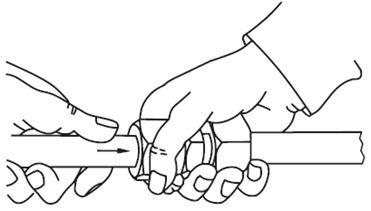 |
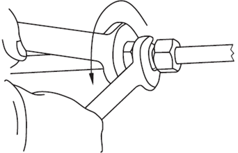
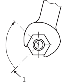
| Step 4:Tightening | Tighten the nut with a wrench according to the recommended number of wrenching turns specified by the manufacturer.Hold the connector body firmly by means of a second wrench or a vise.
NOTE Deviating from the recommended number of assembly turns can lead to reduced pressure performance and life expectancy of the tube connection. Leakage and tube slippage can occur. |
 |
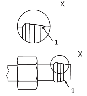
| Step 5:Check | Disassemble the tube connection.Check penetration of cutting edge. If the connector was assembled correctly, a ring of material distributed equally will be visible and should completely cover the front cutting edge.
The cutting ring may turn on tube freely, but it should not be capable of axial displacement. |
 |
| Re-assembly | Each time the connector is disassembled, the nut shall be re-tightened firmly using the same torque as required for initial assembly. Hold the connector body firmly with one wrench, and turn nut with another wrench. |  |
| Minimum length of straight tube end for tube bends | The length of undeformed straight tube (2 × h) shall be at least twice the length of the nut (h).The straight tube end may not exceed any deviation of roundness or straightness which exceeds the dimensional tolerances of the tube. | 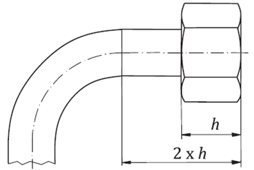 |
2 How to assemble Cutting rings pre-assembly using a manual pre-assembly adapter for final assembly in the 24° cone connector body
| Step 1:Inspection | The cones of manual pre-assembly adapters are subject to the usual wear. Therefore they shall be checked in regular intervals by cone gauges after every 50 assemblies.Non-gauge size adapters shall be replaced to prevent from assembly faults | 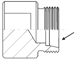 |
| Step 2:Preparation of tube | Cut tube off at a right angle. A maximum angular deviation of 0,5° relative to the tube axis is permissible.Do not use pipe cutters or cutting-off wheels as they cause severe burring and angular cuts. Use of a precision cut-off machine or device is recommended.
Lightly deburr tube ends inside and out (maximum 0,2 × 45°), and clean them. ATTENTION — Thin-walled tubes may require supportive tube inserts; see manufacturer’s assembly instructions. Deformation or irregularities such as inclined sawed-off tubes or excessively deburred tubes reduce the integrity, life expectancy and the sealing of the tube connection. |
 |
| Step 3: Lubrication and orientation | Lubricate thread and 24° cone of the pre-assembly adapter and the thread of the nut.Place nut and cutting ring on the tube with the cutting edge towards the tube end, as shown. Ensure that the cutting ring is facing the correct direction to prevent assembly error. | 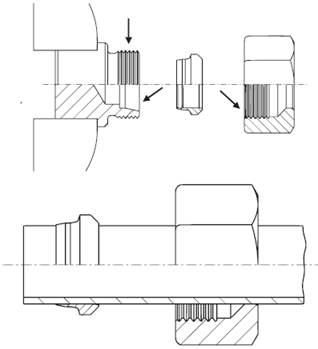 |
| Step 4:Initial assembly | Assemble the nut by hand until contact of the adapter, cutting ring and nut becomes noticeable.Secure the adapter in a vise and insert the tube into the adapter so the tube bottoms out on the tube stop. The tube shall touch the tube stop to ensure that the cutting ring bites into the tube correctly. | 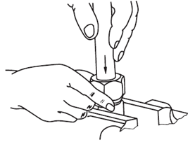 |
| Step 5:Tightening Tighten the nut with a |
Tighten the nut with a wrench according to the recommended number of wrenching turns specified by the manufacturer.NOTE Deviating from the recommended number of assembly turns can lead to reduced pressure performance and life expectancy of the tube connection. Leakage and tube slippage can occur. | 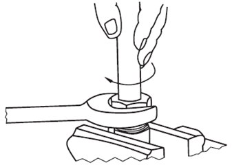 |
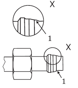
| Step 6:Check | Disassemble the tube connection.Check penetration of cutting edge. If it was assembled correctly, a ring of material distributed equally will be visible and should cover at least 80% of the front cutting edge.
The cutting ring may turn on tube freely, but it should not be capable of axial displacement. |
 |
| Step 7:Final assembly in the connector body | Assemble the nut by hand until contact of connector body, cutting ring and nut becomes noticeable.Tighten the nut according to the recommended number of wrenching turns as specified by the manufacturer from the point of noticeable increase in torque.
Use a second wrench to hold the connector body firmly. NOTE Deviating from the recommended number of assembly turns can lead to reduced pressure performance and life expectancy of the tube connection, leakage and tube slippage can occur. |
 |
| Re-assembly | Each time the connector is disassembled, the nut shall be re-tightened firmly using the same torque as required for initial assembly. Hold the connector body firmly with one wrench, and turn nut with another wrench. | 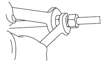 |
| Minimum length of straight tube end for tube bends | The length of undeformed straight tube (2 × h) shall be at least twice the length of the nut (h).The straight tube end may not exceed any deviation of roundness or straightness which exceeds the dimensional tolerances of the tube. | 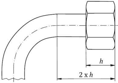 |
3 How to pre-assemble cutting rings using a machine for final assembly in the 24° cone connector body
Best practice regarding reliability and safety is achieved by pre-assembling the cutting rings using machines.
For machines suitable for this operation, along with tools and setup parameters, the connector manufacturer should be consulted.
Post time: Jan-20-2022